
Strain Gage Wind Tunnel Balances – Precision Solutions for the Aerospace Industry
At Modern Machine & Tool Co., Inc. (MM&T), we specialize in designing and manufacturing Multicomponent Strain Gage Wind Tunnel Balances for the aerospace industry. Our one-piece compound balances provide superior accuracy, reliability, and cost-effectiveness compared to traditional multi-piece balances. With decades of expertise in precision measurement, we ensure each balance meets the rigorous demands of aerodynamic testing.


Features of Our Six-Component Wind Tunnel Balances
- Simultaneous and independent measurement of:
- Normal Force
- Axial Force
- Pitch Moment
- Roll Moment
- Yaw Moment
- Side Force
- Strain Gage Bridge Resistances available from 120 Ohms to 5000 Ohms
- Maximum excitation voltage capabilities up to 20 Volts
- Output voltage ranges from 5mV to 20mV Full Scale
- Temperature compensation for span and zero errors from -20°F to +180°F
- Overload safety factors greater than 2:1
- Combined linearity, hysteresis, and repeatability accuracies from 0.1% to 0.5% Full Scale
- Hundreds of stock designs available
- Custom model and sting attachment designs
- Unique balance designs tailored to meet special load or installation requirements
Custom Balances and Specialized Sensors
In addition to our standard multicomponent wind tunnel balances, MM&T offers a range of custom force and moment measuring solutions for aerospace testing:
- External Multicomponent Balances
- Custom Load Cells
- Rotating Multicomponent Balances
- Control Surface Hinge Moment Sensors
- Powered Model Motor Torque and Thrust Balances
- Waterproof Internal Six-Component Balances
- Strain Gaged Composite Wings, Control Surfaces, and Rotor Blades
- Semiconductor Strain Gaging for low-level dynamic signal measurement
- Specialized balances for use in cryogenic environments
- Helicopter rotor balances for six-component measurements of rotating model rotor systems
- Integral force and moment balances for aerodynamic model control surfaces

Typical Six-Component Balance Specifications:
Our Six-Component Wind Tunnel Balances are available in various sizes and specifications to meet diverse testing requirements. Below are typical specifications for balance diameters and load capacities:
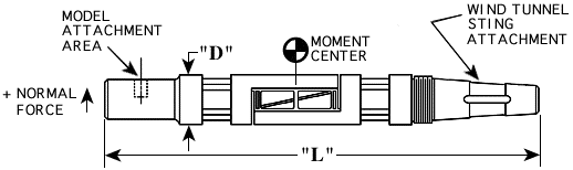
| DIA "D" INCHES | LENGTH "L" INCHES | LOAD (LB or IN.LB) | AXIAL FORCE | PITCH MOMENT | PITCH MOMENT | YAW MOMENT | SIDE FORCE |
|---|---|---|---|---|---|---|---|
| 0.400 | 3.750 | 3 | 2 | 5 | 3 | 3 | 2 |
| 0.500 | 4.700 | 75 | 15 | 75 | 15 | 25 | 25 |
| 0.750 | 6.250 | 150 | 30 | 200 | 50 | 100 | 75 |
| 1.000 | 8.375 | 400 | 100 | 600 | 100 | 200 | 100 |
| 1.250 | 10.000 | 600 | 200 | 1500 | 400 | 700 | 300 |
| 1.500 | 11.500 | 1500 | 300 | 2500 | 800 | 1200 | 600 |
| 1.750 | 12.250 | 2000 | 400 | 3500 | 1500 | 2000 | 800 |
| 2.000 | 12.750 | 3000 | 500 | 7500 | 3000 | 3000 | 1200 |
| 3.000 | 24.250 | 3000 | 500 | 25000 | 10000 | 10000 | 1100 |
| 4.000 | 24.250 | 5500 | 500 | 40000 | 24000 | 12000 | 1000 |
| 5.000 | 26.000 | 7500 | 3500 | 90000 |
